Recently we were moving our office and in the new place there was a RFID reader that went to the thrash. I took it to see if I can make it read the several RFID cards I have… Here is what I did.
I did some research on the hardware and what it does. Here is what I found out.
The HID ThinLine II Reader
Looking at the datasheet on HID’s web-site, I have noticed the following:
- There are two types of data interfaces – Wiegand (model 5395) and Clock and Data (model 5398). The one I’ve got is 5395.
- 125 kHz transmit frequency
- Power supply 5-16 VDC
The following wiring is specified:
- 5-12 VDC – RED
- GROUND – BLACK
- DATA0/DATA – GREEN
- DATA1/CLOCK – WHITE
- SHIELD GROUND – DRAIN
- GREEN LED – ORANGE
- RED LED – BROWN
- BEEPER – YELLOW
- HOLD – BLUE
- CARD PRESENT – VIOLET
The Wiegand mystery
Reading around the web I was somewhat confused about what Wiegand is. Is it a protocol? Wiring scheme? Card encoding? Something completely different?
A little Wikipedia helped fill in some of the gaps. Apparently John Richard Wiegand discovered the magnetic effect used nowadays reading the RFID cards. There is also a Wiegand Interface which is used for the wiring of the card readers to another system and also the Wiegand protocol specifying how the data is transmitted on the Wiegand interface. Oh my, there is also a Wiegand 26-bit format (but apparently companies made extensions to 34-bit, 37-bit, etc. which are not very standardized), which is commonly supported. Some companies use the format with as many as 50-bits!
The Wiegand Interface
There are three wires in the Wiegand interface (GROUND, DATA0, and DATA1). Both DATA0 and DATA1 have +5V when not transmitting. DATA0 and DATA1 are send a low (almost zero) pulse when transmitting 0 or 1 respectively. The requirement is for the pulses to not overlap (I sure hope they don’t).
The signal for transmitting 010 should look something like this:
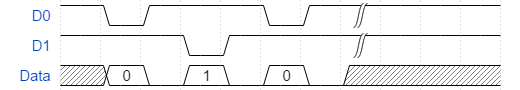
As far as I can gather the pulse widths vary by reader and can be 20-100μs and the pulse interval 200μs-20ms.
The transmitting continues until all bits are transmitted.
The Wiegand Formats
There are many variations of the non 26-bit Wiegand formats, but I will try to show you what I have found, so it will at least get you started.
Wiegand 26 Format
This one is the pretty much standard format that everyone supports, but I don’t think is used much anymore. None of the cards I’ve got are in this format, although I did find a very old one to test with. Here are the bits
| Bits | Count | Purpose |
|---|---|---|
| 1 | 1 | Even parity over bits 2 to 13 |
| 2-9 | 8 | Facility code (0 to 255); Bit 2 is MSB |
| 10-25 | 16 | Card Number (0 to 65535); Bit 10 is MSB |
| 26 | 1 | Odd parity over bits 14 to 25 |
The parity bits work as follows:
- Bit #1 is even parity, so if the number of bits set to 1 in bits 2-13 is odd, then this bit is set to 1.
- Bit #1 is odd parity, so if the number of bits set to 1 in bits 10-25 is even, then this bit is set to 1.
Here are an example 26-bit code received:
1101111011110011010011101
Even Parity: 1 (10111101111 has odd number of 1s, hence the 1)
Facility Code: 1011110 (94)
Card Code: 1111001101001110 (62286)
Odd Parity: 1 (001101001110 has even number of 1s, hence the 1)
Does it start to make sense?
Other Wiegand formats are a guess and without knowing the exact configuration, it would be difficult to say what is the facility number and what is the card number. Here is some more information on the HID cards and their markings. In general they are marked with something like
CCCCCC XXXXXXXXXX-YY
, where CCCCCC is the card number and XXXXXXXXXX-YY is the order number. For the cards I experimented with that have 32, 35, and 37 bits, the card code seems to match the printed one if I use 20 bits for the card code in all instances, although this might be pure luck. You’d need to experiment some.
As far as I understand, cards can be made with any user-defined configuration.
This is getting long, so I will write another post with how I used an Arduino UNO to read the cards.